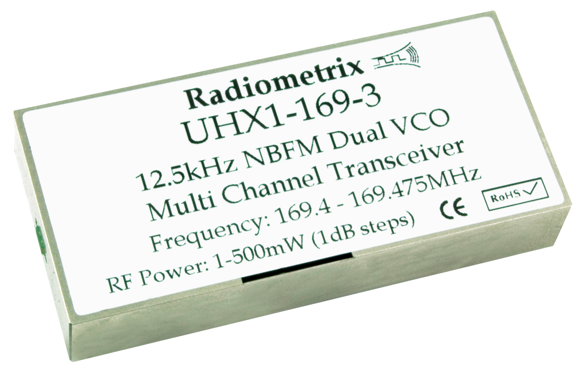
UHX1
NBFM Multichannel 500mW VHF Transceiver
UHX1 is small dual frequency multi-channel VHF transceiver with up to 500mW RF power output.
The dual frequency capability allows UHX1's transmitter section to be operated on one frequency while receiver frequency on another.
Features
- Conforms to ETSI EN 300 220-3 and EN 301 489-3
- High performance double superhet, 128 channel PLL synthesizer
- 500mW RF power output: adjustable via serial command
- Data rates up to 5 kbps for standard module
- Usable range over 1km
- Fully screened
- Feature-rich interface (RSSI, analogue and digital baseband)
- Digital RSSI output
- Incorporates a 1200baud dumb modem
- Re-programmable via RS232 interface
- Low power requirements
- TX enable LED indicator
Applications
- Handheld terminals
- Heavy vehicle/machine remote controls
- EPOS equipment, barcode scanners
- Data loggers
- Industrial telemetry and telecommand
- In-building environmental monitoring and control
- High-end security and fire alarms
- Vehicle data up/download
Technical Summary
- Operating frequency: Any 2MHz segmnet in 140- 175MHz
- 128 channels controlled via RS232 interface
- 16 channels selected by parallel interface
- Transmit power: : 500mW (+27dBm) nominal. Adjustable 1 - 500mW
- Supply range: 5V regulated transmit, 3.1 - 15V receive
- Current consumption: 330mA (at 500mW output) transmit, 25mA receive
- Data bit rate: 5kbps max. (standard module)
- Receiver sensitivity: -118dBm (for 12 dB SINAD)
- Size: 67 x 30 x 12mm
Evaluation Platform: Narrow Band Evaluation Kit
Figure 3: UHX1 footprint (Top)
Pin Description
RF & TX supply | ||||
Pin | Name | Normal mode | Serial mode (programming) | Modem mode |
1A | RF Gnd | RF ground | ||
2A | RF in/out | To the antenna | ||
3A | RF Gnd | RF ground | ||
4A | GND | 0V | ||
5A | GND | 0V | ||
6A | Vcc (TX) | 5V regulated supply for TX | ||
USER | ||||
1 | TXD | DC copled input for TTL/COMS logic | NC | |
2 | TXE | Transmit enable. Low = TX (47kW pullup) | NC | |
3 | GND | 0V | ||
4 | Vcc | DC supply input. (3.1 - 15V) | ||
5 | P3 | Parallel channel select MSB | Serial read back | BYSY |
6 | P2 | Parallel channel select | TBA | MOD TXD |
7 | P1 | Parallel channel select | TBA | MOD RXD |
8 | P0 | Parallel channel select LSB | PGM in | PGM in |
9 | RSSI | DC level between 0.5V and 2.5V. 60dB dynamic range | ||
10 | RXD | Open collector output of data slicer. | NC | |
11 | AF out | 500mVp-p audio. DC coupled, approx. 0.8V bias |
NOTES:
1. No inversion occurs between TXD and RXD. However, AF out is inverted relative to mod in.
2. P0 - P3 (parallel channel selects) and TXE are active LOW and have internal 47K pullups to 3v.
3. Open collector output RXD has a 47K pullup to 3v.
4. The software incorporates a 1200baud dumb modem, compatible with that implemented in other Radiometrix narrowband units ( i1200 tones and format ). Modem operation is selected by a serial command.
5. Main serial port (P0-P3) operates at 9600 baud. (Command set is not the same as TR2M, SMX families). The unit is capable of operating in 'basic' parallel channel select only mode, or in serial controlled 'expanded' mode.
6. Transmit power can be set by serial command.
7. RSSI, and other status information, can be read back as a digital value. (on P3).
7a. The RSSI is a high impedence output. If a low impedence voltage source (an op-amp output) is connected to the RSSI out pin then this voltage (0-2.5v) will override the RSSI value during RSSI 'digital read' operations.
8. If analogue transmit modulation is needed, then connect a series 1uF cap + 500K trimmer (a multiturn is advised) in the 'baseband TXD' circuit. Adjust trimmer for 90% of peak deviation (+/- 2.7KHz) at mean input level.
9. The high current (250mA max.) transmitter supply (5v regulated) is fed to a separate connector
10. A version without a RX/TX switch is available. This unit has a 4 pin RF connector (RX, GND, TX, GND) and is intended for use with external power amplifiers
UHX1 serial interface details (version 4): PRELIMINARY
The UHX1 user interface is accessed through the four parallel pins (P0/serial through P3).
It has four operating modes:
1. Parallel
Frequency of operation is selected as one of 16 (chans 0-15), by means of a 4 bit inverted value applied to P0-P3. The P0 pin will also respond to a LOCKSERIALMODE datastream (inverted RS232, 9600 baud), which will cause the radio to enter serial mode. In parallel mode, the IDENT command string is still decoded, but the unit remains in parallel mode.
2. Serial
Frequency of operation, radio set up, power output and various other parameters are controlled by command strings sent to P0. Pin P3 functions as a 'readback' port while P1,2 are not used in this mode.
In this mode, decimal values are used (to simplify direct manual programming via a terminal)
Commands include:
Commands | Function | Note |
: | empty command buffer | |
? or / | read back buffer contents | |
<backspace> | delete last character | |
<cr> | process buffer | |
PARALLEL | return to the basic, parallel mode (and turn modem off) | |
DUMP | read back contents of eeprom (output on P3) | |
MODEM | activate 1200 baud modem | # |
NOMODEM | de-activate 1200 baud modem | # |
DEFCH ccc | set default channel (non-volatile) | # |
DEFPOW pp | set default tx power (non-voltatile) | # |
CHAN ccc | jump to channel (volatile) | |
POWER pp | select tx power (volatile) | |
RSSI | single read of RSSI (output on P3) | |
SHORT | enter short command mode | # |
(The following commands are used to set up the radio operating characteristics, and should be viewed with caution. Especially the CALPOWER command, which initiates a multiple write operation to the power calibration table )
mmands | Function | Note |
NDIV nnnnn | force N divider value (volatile) | |
RDIV rrrrr | force R divider value (volatile) | |
RLOAD rrrrr | Set R divider value | # |
OFFSET ooooo | Set RX offset | # |
LOAD aa nnnnn | Set N values for first 16 channels | # |
START nnnnn | Set N value for ch 16 | # |
STEP i | Set increment for table | # |
LIMIT ccc | Set highest permitted channel number | # |
SETPOW eee | Set maximum power output (100mW) | |
CALPOWER (etc) | (see factory procedures for more details) | |
TEST | Generate a 250Hz test modulation (only fuctions in TX mode, cancelled by sending a <cr> byte) | |
IDENT | Readback a single byte, depending on current mode: | |
Parallel: P | ||
Serial: S | ||
Short: 1 | ||
Modem: |
(Channels 0-15 are individually programmed by the LOAD operation. Channels 16-127 are a consecutive table, using the START value as a start point (=channel 16) and increasing the N value by STEP with each increase in channel number)
ccc = a channel number from 00 to 127
aa = a two digit channel number from 00 to 15
nnnnn = synthesizer N register value, (up to 65535)
rrrrr = synthesizer R register value, (up to 16383)
pp = power setting value (0 - 30)
i = table step (increments of N) (0-7)
ooooo = receive mode frequency offset
eee = power calibration figure
N = channel frequency / (13MHz / R)
10MHz / R = 25KHz , so R = 400 (usually)
receive OFFSET = 21.4MHz / (13MHz / R) , so = 856 (usually)
A pause of at least 50mS must be allowed after operations which result in eeprom programming operations (all except NDIV, RDIV, GOTO, PSET and RSSI). This allows the programming cycle to complete.
Instructions marked ' # ' output a three byte ' OK<cr> ' sequence after sucessfully completing their eeprom programming cycles
When first powered up, the unit will operate on channel and output level specified by the last CHAN and POWER instructions, irrespective of previous NDIV, RDIV, CHAN or PSET operations)
3. Short
A limited range of radio functions are controlled by sending a single byte to P0
Commands | Function | Note |
0 - 127 | select channel | volatile |
128 - 159 | select power ( = byte -128) | volatile |
200 | single read of RSSI | output on P3 |
201 | single byte read, as for IDENT command | |
222 | reception of 16 consecutive 222 bytes returns radio to serial mode |
4. Modem
Commands are interpreted as in SERIAL mode (and 'short' mode may be selected.) In this mode the unit operates as a simple 1200 baud packet modem, with TXD (in) on P2 and RXD (out) on P1.
The TXE pin does not control tx switching in this mode, but rather the presence of valid data in the tx buffer initiates a transmit burst. No handshaking is provided, and the unit has a sufficient over-link data rate to transparently 'stream' continuous data. Error correction, re-transmission of corrupt packets and addressing are not provided.
This mode is compatible with other Radiometrix 'i 1200' mode equipment, including the narrow band eval kit.
NOTES:
- The LOCKSERIALMODE (and FAST) commands are non-volatile. Once a serial mode is selected, the unit will power up in this mode until a PARALLEL command is received.
- The command interpreter IS case sensitive. Use upper case.
- Spaces are optional (they are not decoded), provided the command line does not exceed 16 characters.
- When manually programming this unit we recommend setting your terminal to local echo. The 'backspace' key functions normally.
- All serial communications use 9600baud 'inverted RS232' 8 bit data, no parity, 1 start bit, 1 or 2 stop bits
- A simple 'driver' program will be made available to simplify programming of these units, if desired.
- RSSI read operations only function correctly if the unit is in RX mode (TXE pin is high or floating
Condensed specifications
Frequency | Any 2MHz segment in 140 - 175MHz (TX and RX frequencies need not be the same) |
Frequency stability |
+/-5ppm (better than ±1.5kHz) |
Channel spacing
|
20kHz or 25kHz (12.5kHz by special order) |
Number of channels
|
128 channels by serial RS232 interface or 16 by parallel select |
Supply Receive | 3.1 -15V at 24mA |
Transmit | 5.0V regulated 55mA (at 10mW output) 270mA (at 500mW output) (plus 20mA at 3.6-15v from pin4: Vcc) |
Operating temperature | -20 to +70 °C (Storage -30 to +70 °C) |
Spurious radiations | Compliant with ETSI EN 300 220-3 and EN 301 489-3 |
Size | 67 x 30 x 12mm |
Interface user | 11pin 0.1" pitch molex |
RF and TX supply |
6pin 0.1" pitch molex |
Reprogram |
5pin 0.1" pitch molexsocket in top case |
Recommended PCB hole size | 1.2mm |
Transmitter | |
Output power |
500mW (+27dBm); Adjustable via serial command 1 - 500mW in 1dB steps) |
TX on switching time | <50 ms |
Modulation type | FM, FSK (F1D, F3D) |
TX modulation bandwidth | DC - 3kHz |
Deviation | ±3kHz (±1.5kHz for 12.5kHz channel variant) |
Adjacent channel TX power | -37dBm |
TX spurii | <-40dBm |
Inputs | Data (CMOS/TTL compatible) |
Receiver | |
Sensitivity | -118dBm for 12 dB SINAD |
image / spurious | -65dB |
blocking | -86dB |
adjacent Channel | <-65dB (Tested per. ETSI EN 301 489-3) |
outputs | RSSI, audio, data |
Dynamic timing: | |
RX data recovery settling time | 20ms |
Power on to stable (50:50 mark / space) RXD | 50ms (TXE low/active to stable RX data out) |
Maximum time between data transitions | 250ms |
Limitation of liability
The information furnished by Radiometrix Ltd is believed to be accurate and reliable. Radiometrix Ltd reserves the right to make changes or improvements in the design, specification or manufacture of its subassembly products without notice. Radiometrix Ltd does not assume any liability arising from the application or use of any product or circuit described herein, nor for any infringements of patents or other rights of third parties which may result from the use of its products. This data sheet neither states nor implies warranty of any kind, including fitness for any particular application. These radio devices may be subject to radio interference and may not function as intended if interference is present. We do NOT recommend their use for life critical applications.
The Intrastat commodity code for all our modules is: 8542 6000.
R&TTE Directive
After 7 April 2001 the manufacturer can only place finished product on the market under the provisions of the R&TTE Directive. Equipment within the scope of the R&TTE Directive may demonstrate compliance to the essential requirements specified in Article 3 of the Directive, as appropriate to the particular equipment.
Further details are available on The Office of Communications (Ofcom) web site:
Licensing policy manual